

Position Sensors
- Muhammad Shahid
- m_shahid@live.co.uk
- 12 min
- 76 Views
- 0 Comments
- 15 Likes

Introduction
In this article, we will look at a variety of devices that fall under the category of Input Devices and are consequently referred to as “Sensors,” with a focus on Position sensors.
The Position Sensor, as its name suggests, detects the position of objects, indicating that they are either referred to or from a fixed point or location. Sensors of this kind offer “Positional” feedback.
Using “distance,” which can be the distance between two locations, such as the distance traveled or moved away from a fixed point, or “rotation” (angular movement) are two ways to determine a position. For instance, a robot’s wheel rotates to measure how far it has traveled on the ground. Position sensors can either use linear sensors to detect an object’s movement in a straight line or rotational sensors to detect an object’s angular movement.
The Potentiometer As a Position Sensor
The potentiometer is the most widely utilized of all the “Position Sensors” due to its low cost and simplicity of usage. Utilizing a wiper contact connected to a mechanical shaft, it can move down a track in either an angular (rotational) or linear (slider) fashion.
As a result of this movement, the resistance value between the wiper/slider and the two end connections changes, producing an electrical signal output that is proportionate to the wiper’s actual location on the resistive track. Stated differently, resistance increases with physical position.

Potentiometers are available in a variety of sizes and designs, including the longer, flat linear slider versions and the widely used circular rotating form. The movable item is directly attached to the potentiometer’s slider or rotating shaft when it is being utilized as a position sensor.
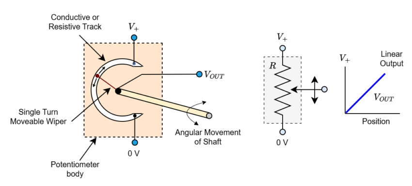
The resistive element is formed by applying a DC reference voltage across the two outer fixed connections. As seen here, the wiper terminal of the sliding contact provides the output voltage signal.
This arrangement results in a circuit output of the potential or voltage divider type that is proportional to the shaft position. The potentiometer’s resistive element, for instance, would produce a maximum output voltage of 10 volts, which would be equivalent to the supply voltage at that level, and a minimum output voltage of 0 volts. The output signal will then fluctuate between 0 and 10 volts due to the potentiometer wiper, with 5 volts signifying that the wiper or slider is at its halfway or center position.
Potentiometer Construction
As the potentiometer travels down the resistive track, the center wiper connection provides the output signal (Vout), which is proportionate to the shaft’s angular position.

Although resistive potentiometer position sensors are inexpensive, low-tech, and simple to use, they also have several drawbacks as position sensors, including limited frequency response, low precision, low repeatability, and wear from moving parts.
However, the potentiometer’s use as a location sensor has one major drawback. The physical size of the potentiometer being used determines the wiper or slider’s range of motion (and, consequently, the output signal produced).
A single-turn rotational potentiometer, for instance, often only has a fixed mechanical rotation of 0° to a maximum of 240° to 330°. Nevertheless, multi-turn pots with a mechanical rotation of up to 3600o (10 x 360o) are also available.
Most potentiometers use carbon film for their resistive track; however, these devices have a limited mechanical life and are electrically noisy (like the crackle on a radio volume control).
Wire-wound pots, also called rheostats, can be made of resistive wire or straight wire. However, they have resolution issues because their wiper jumps from one wire segment to the next, generating a logarithmic (LOG) output that causes errors in the output signal. Electrical noise also affects them.
There are now conductive plastic resistance element type polymer film or ceramic type potentiometers available for high precision low noise applications. These pots are available as single-turn or multi-turn devices and have a low friction electrically linear (LIN) resistive track that provides low noise, long life, and great resolution. Steering wheels, industrial applications, robots, and computer gaming joysticks are typical uses for this kind of high-precision position sensor.
Inductive Position Sensor
Linear Variable Differential Transformer
“Linear Variable Differential Transformer,” or LVDT for short, is one kind of positioning sensor that is not affected by mechanical wear issues. Similar to the AC transformer used to monitor movement, this inductive-type position sensor operates on the same principle. Its output is proportionate to the location of its movable core, making it an extremely precise tool for measuring linear displacement.
In simple terms, it is made up of three coils coiled on a hollow tube former. The main coil is formed by one coil, and the other two coils create identical secondary that are linked electrically in series but 180 degrees out of phase on either side of the primary coil.
Inside the LVDT’s tubular body, a movable soft iron ferromagnetic core—also referred to as an “armature”—that is attached to the item being measured slides or moves up and down.
The main winding receives a little AC reference voltage known as the “excitation signal” (2–20V rms, 2–20kHz), which causes an EMF signal to be induced into the two nearby secondary windings (transformer principles).
When the soft iron magnetic core armature is in the “null position,” which is precisely in the middle of the tube and the windings, the two induced electromagnetic fields in the two secondary windings cancel each other out since they are 180 degrees out of phase, resulting in a zero-output voltage. An output will be generated when the induced voltage in one of the secondaries becomes higher than that of the other secondary due to the core being slightly moved to one side or the other from this null or zero state.
The direction and displacement of the moving core determine the output signal’s polarity. The output signal will increase in proportion to the amount of displacement of the soft iron core from its null center location. The output differential voltage changes linearly with the location of the cores consequently. Consequently, the output signal from this kind of position sensor has a polarity that specifies the direction of movement in addition to an amplitude that is a linear function of the core’s displacement.
To determine which half of the coil the magnetic core is in and, consequently, the direction of travel, appropriate electronic circuits, such as the AD592 LVDT Sensor Amplifier, may compare the output signal’s phase to that of the primary coil excitation phase.

The output voltage varies from maximum to zero and back to maximum as the armature is moved from one end to the other through the center position, while the phase angle also changes by 180 degrees throughout this process. This allows the LVDT to provide an output AC signal whose phase angle indicates the core’s direction of travel and whose amplitude indicates the degree of displacement from the center position.
As a pressure transducer, a linear variable differential transformer (LVDT) sensor is commonly used to detect pressure by pushing on a diaphragm to generate force. The sensor subsequently transforms the force into a voltage signal that can be read.
When compared to a resistive potentiometer, the linear variable differential transformer, or LVDT, has the following advantages: great linearity, or the ratio of voltage output to displacement; extremely good precision; superb resolution; high sensitivity; and frictionless operation. For usage in harsh conditions, they are also sealed.
Inductive Proximity Position Sensor
The Inductive Proximity Sensor, also known as an Eddy Current Sensor, is another popular kind of inductive position sensor. The term “proximity sensor” refers to the fact that they are primarily employed to detect the presence of an item in front of them or inside close proximity, even if they do not measure displacement or angular rotation.
A magnetic field is used by proximity sensors, which are non-contact position sensors. The most basic type of magnetic sensor is a reed switch. An inductive loop is created in an inductive sensor by winding a coil around an iron core in an electromagnetic field.
The inductance of the coil varies dramatically when a ferromagnetic substance, such as a metal screw or plate, is positioned inside the eddy current field created around the inductive sensor. This change is detected by the proximity sensor detecting circuit, which generates an output voltage. Consequently, Faraday’s Law of Inductance, an electrical concept, governs how inductive proximity sensor’s function.

The four primary components of an inductive proximity sensor are the coil, which creates the magnetic field, the oscillator, which creates the electromagnetic field, the detection circuit, which detects any change in the field when an object enters it, and the output circuit, which generates the output signal with either normally closed (NC) or normally open (NO) contacts.
Without making direct contact with the object that is being detected, inductive proximity sensors may detect metallic objects in front of the sensor head. They are therefore perfect for use in soiled or damp conditions. Proximity sensors have a relatively narrow “sensing” range, usually between 0.1 and 12 mm.

In addition to their industrial uses, inductive proximity sensors are frequently employed to regulate traffic flow through the alteration of traffic signals at intersections and crosswalks. Wire loops that are rectangular and inductive are embedded in the tarmac road surface.
The metallic body of an automobile or other road vehicle alters the inductance of the loop as it passes over it, activating the sensor and notifying the traffic light controller that a vehicle is waiting.
These position sensors are “omnidirectional” in nature, which allows them to detect metallic objects either above, below, or to the side of them, which is one of their primary drawbacks. Additionally, despite the availability of Capacitive Proximity Sensors and Ultrasonic Proximity Sensors, they are unable to identify non-metallic items. Reed switches, Hall Effect Sensors, and variable reluctance sensors are further widely accessible magnetic positional sensors.
Rotary Encoders As A Position Sensor
Another kind of position sensor is a Rotary Encoder, which is a non-contact optical device that converts the angular position of a rotating shaft into an analog or digital data code. It is similar to the potentiometers discussed above. Started differently, they transform mechanical motion into an electrical signal, ideally digital.
Every optical encoder operates using the same fundamental idea. A revolving high-resolution encoded disk with the necessary code patterns—binary, grey code, or BCD—is exposed to light from an LED or infrared light source. As the disk spins, photo detectors scan it. An electrical circuit then converts the data into a digital stream of binary output pulses, which are then sent to counters or controllers to ascertain the shaft’s precise angular location.
There are two basic types of rotary optical encoders, Incremental Encoders and Absolute Position Encoders.
Incremental Encoder

Incremental encoders, often referred to as relative rotary encoders or quadrature encoders, are the more basic of the two position sensors. As the coded disk, which has clear and dark lines called segments on its surface that are uniformly spaced, travels or spins past the light source, it produces a sequence of square wave pulses. The encoder generates a series of square wave pulses that, when tallied, reveal the rotating shaft’s angular location.
Two distinct outputs known as “quadrature outputs” are present in incremental encoders. The output sequence is used to calculate the shaft’s rotational direction, and these two outputs are displaced 90° degrees out of phase with one another.
The device’s resolution is determined by the number of transparent and dark segments or slots on the disk; the more lines in the pattern, the higher the resolution per degree of rotation. The resolution of most encoded discs is up to 256 pulses, or 8 bits per spin.
A tachometer is the most basic type of incremental encoder. It is frequently utilized in unidirectional applications where just minimal position or speed information is needed, and it has a single square wave output. The more popular “quadrature” or “sine wave” encoder has two output square waves, which are referred to as “channel A” and “channel B.” The device generates two distinct sine and cosine output signals by using two photodetectors that are 90 degrees apart.
Simple Incremental Encoder

The angle of the shaft in radians may be computed using the Arc Tangent mathematical function. Since rotary position encoders typically employ a circular optical disk, the output resolution is expressed as follows: θ = 360/n, where n is the number of segments on the coded disk.
As an example, the number of segments needed to provide a resolution of 1o to an incremental encoder is 1o = 360/n, meaning that n = 360 windows, etc. Additionally, the direction of rotation may be ascertained by observing which channel generates an output first, either channel A or channel B, which provides two rotational directions: A leads B or B leads A. The layout is seen below.
Incremental Encoder Output

When employed as a position sensor, incremental encoders have the primary drawback of requiring external counters to calculate the shaft’s absolute angle inside a specific rotation. The resultant angular information will result in an error if the power is briefly turned off, or if the encoder misses a pulse because of noise or a dirty disk. Using absolute position encoders is one method to get around this drawback.
Absolute Position Encoder
Compared to quadrature encoders, Absolute Position Encoders are more complicated. They offer a distinct output code that indicates both position and direction for each rotational position. Multiple concentric “tracks” of light and dark segments make up their coded disk. To concurrently read a distinct coded position value for every angle of movement, each track has its separate light detector. A 12-bit absolute encoder would have 12 tracks, and the same coded value would only show once every revolution. This is because the number of tracks on the disk is correlated with the binary “bit”-resolution of the encoder.
4-bit Binary Coded Disc

One major benefit of an absolute encoder is its non-volatile memory, which keeps the encoder in its precise location without requiring it to return to its “home” position in the event of a power outage. The majority of rotary encoders are classified as “single turn” devices; but there are also multi-turn systems that use additional code disks to collect feedback across several rotations.
Absolute position encoders are commonly used in printers and plotters to precisely position the printing heads over paper, or in computer hard drives and CD/DVD drives to monitor the absolute position of the drivers’ read/write heads.
We have examined some sensors that may be used to determine the presence or location of objects in this Position Sensor lesson. The following lesson will examine temperature-measuring sensors, also referred to as temperature sensors, which include thermistors, thermostats, and thermocouples.
Summary
- Position sensors detect the position of objects based on distance or rotation. They provide positional feedback by measuring linear or angular movement.
- Potentiometers are commonly used position sensors due to their affordability and simplicity. They use a wiper contact on a resistive track to produce an electrical signal proportional to position but face limitations like wear and noise.
- The Linear Variable Differential Transformer (LVDT) is a precise, frictionless position sensor unaffected by mechanical wear. It generates output voltage based on the displacement of a movable core.
- These sensors detect nearby metallic objects using electromagnetic fields without physical contact. They are commonly used in industrial settings and traffic control systems.
- Rotary encoders convert angular positions into electrical signals. Incremental encoders provide relative position data, while absolute encoders offer precise position information even after power loss.
- Position sensors find extensive use in robotics, automotive systems, industrial machinery, and gaming devices. While some offer high accuracy and durability, others may suffer from noise, limited lifespan, and restricted resolution.
Please follow and like us:
More tutorials in Input/Output Devices
Subscribe
Login
0 Comments